Summary of the Hovitron project
System Architecture
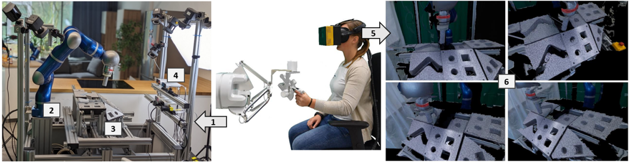 |
| Figure 1: Guiding (1) the robot arm (2) in the scene (3), captured with fixed RGBD cameras (4), and providing for each head pose (5) the corresponding stereoscopic and holographic viewpoints (6) through view synthesis technology. |
Figure 1 summarizes the HoviTron targets, focusing on two aspects: “Hovi” referring to Holographic Vision, and “Tron” corresponding to Tele-Robotic Operation. The “Tron” target imposes that a tele-operator can freely navigate in the scene, while the “Hovi” target adds eye accommodation to the stereoscopic viewing.
In the final Proof-of-Concept (PoC-3), the HoviTron tele-operator remotely guides (1) the robot arm (2) in the scene (3) that is captured by fixed RGBD devices (4). The head pose (5) determines the viewpoints (6) to synthesize for the Head Mounted Display (HMD), conferring free navigation. The stereoscopic view synthesis is augmented with micro-parallax foveated images – aka a light field - that provide immersive holographic vision to the tele-operator, therefore experiencing less workload than with a conventional stereoscopic head mounted display.
The HoviTron website (hovitron.eu) shows an introductory movie (cf. Figure 2) about HoviTron’s challenges and technology, further explained in the remainder of the document. The robotic hardware has been provided by DLR (Deutsches Zentrum für Luft und Raumfahrt), while CREAL (Swiss start-up in light field display technology) developed the light field head mounted display (and OpenXR software driver) for Holographic Vision. Most of the software development was done by UPM (Universidad Politécnica de Madrid) and ULB (Université Libre de Bruxelles).
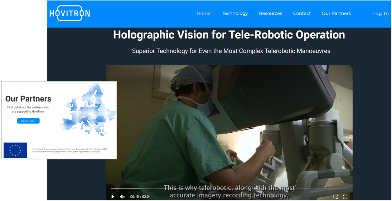 |
| Figure 2: HoviTron website introductory movie |
An important new hardware development was the light field Head Mounted Display (HMD) for Holographic Vision, by CREAL. As shown in Figure 3, it projects 32 images with micro-parallax in each eye, that get slightly shifted through the eye-lens to confer focus on the object of interest. For instance, since the Wikipedia sphere of Figure 4 has small disparity \(d_1\) (like what happens between the two eyes in stereo vision), while the (virtual) robotic finger has relatively large disparity \(d_2\), the micro-parallax images will be realigned through the eye-lens to get one or the other object in focus on the retina, never both together. This phenomenon mimics natural eye accommodation on top of the free navigation functionality, described before.
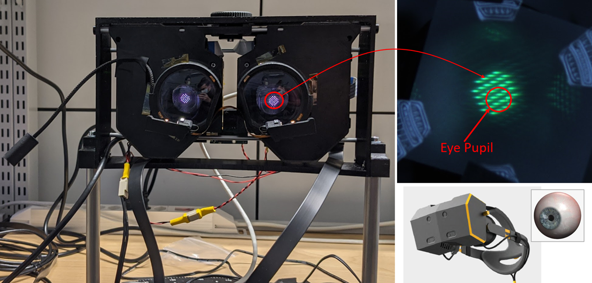 |
| Figure 3: Projection of 32 micro-parallax images in each eye of the light field head mounted display. |
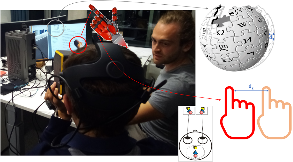 |
| Figure 4: The difference in parallax between distant and nearby objects will realign only one of these objects, observed as sharp in the eye accommodation process. |
Snapshots of the free navigation functionality in the HoviTron Proof-of-Concept (PoC-3) are shown in Figure 5. There are small black regions artefacts because of imperfect depth sensing, but this is perfectly acceptable in robotic applications; it would be more annoying in aesthetic rendering for entertainment applications.
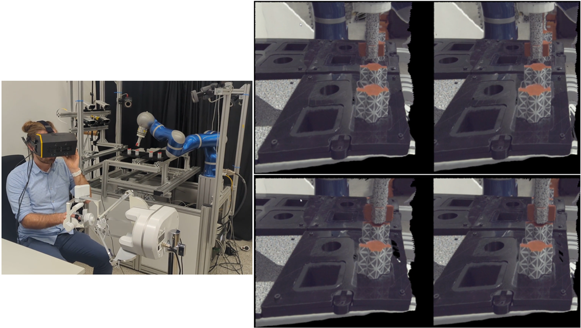 |
| Figure 5: Tele-robotic operation (left) and corresponding stereoscopic views in the head mounted display (right). Holographic Vision results cannot be shown here: “One has to see it to believe it” (a teaser is shown in Figure 7). |
Figure 6 further shows the eye accommodation functionality with focus on foreground (a) and background objects (b). The focus changes are small - a reality in the human visual system - but sufficiently large as to acquire a high visual comfort, as was confirmed in the User Studies (US-1 and US-2). Figure 7 shows a zoom-in to better apprehend the effect, rearranging the images to see foreground and background focus side-by-side.
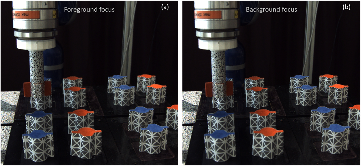 |
| Figure 6: Each view supports eye accommodation with focus on the foreground (left – a) or background (right – b). |
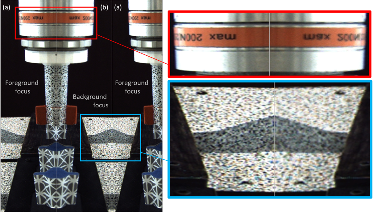 |
| Figure 7: Zoom-in on foreground/background focus by rearranging the views (a) and (b) of Figure 6. |
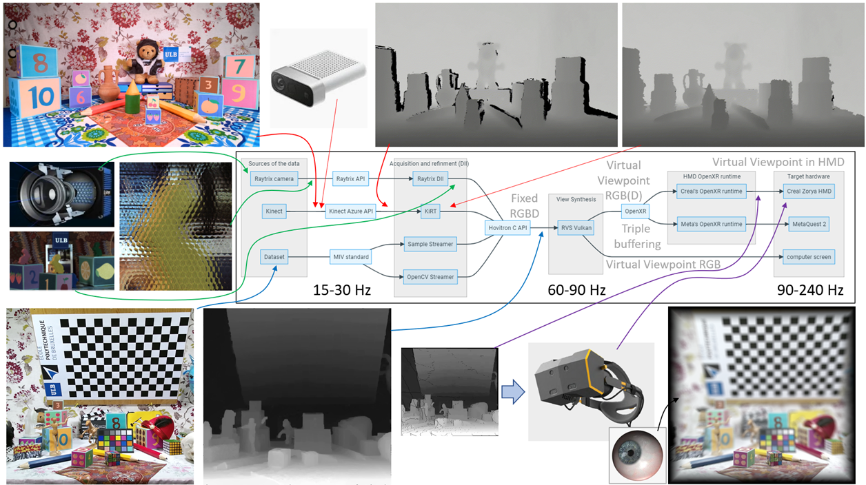 |
| Figure 8: HoviTron software architecture with various acquisition and rendering modalities. |
The acquisition and rendering processing tools have been embedded in HoviTron’s modular software architecture of Figure 8 with Dynamic Link Libraries (DLL) running on various Graphical Processing Units (GPUs) of the multi-GPU PCs dedicated to the project. In the minimal setting of the final Proof-of-Concept PoC-3, two GPUs suffices for reaching the target real-time performances of 30 fps in stereoscopic viewing, cf. deliverable D5.5, while a third GPU is highly recommended to properly serve the Holographic Vision in CREAL’s light field HMD at high frame rates (up to 240 fps). More advanced settings with up to eight GPUs are reported in deliverable D4.2.
Software processing modules
The modular software pipeline of Figure 8 confers a lot of flexibility w.r.t. the input-output configuration options: Azure Kinect vs. RayTrix camera input; TV screen, stereoscopic HMD or Holographic Vision light field HMD output. The modularity also ensures that various multi-GPU configurations can easily be set without complete recompilation of the software pipeline.
In this section, we briefly describe a couple of core modules and their internal working principles.
RVS = Reference View Synthesizer
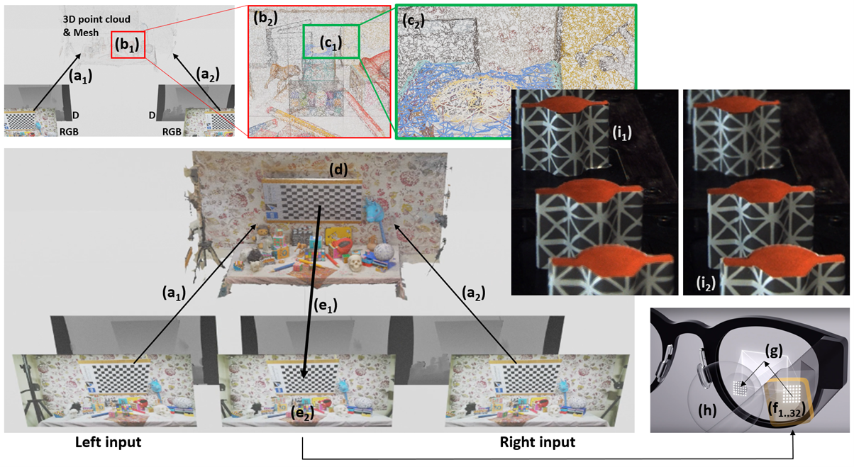 |
| Figure 9: Virtual view synthesis (\(e_2\)) from a couple of input images (Left-Right, cf. bottom) through 2D-3D back- and forth projection (\(a_1\)-\(a_2\)) and implicit meshing (\(b_1\)-\(b_2\)-\(c_1\)-\(c_2\)) in its 3D representation (d). Micro-parallax virtual views (\(f_{1..32}\)) projected through a smart optical system (g) into the eye (h) create a light field, enabling Holographic Vision with back- and foreground eye accommodation (\(i_1\)-\(i_2\)). |
Figure 9 explains how our RVS (Reference View Synthesizer) OpenGL tool donated to MPEG-I and further developed within HoviTron (mainly a Vulkan equivalent with extensions) synthesizes virtual views. In a nutshell, RGBD data captured from a fixed set of cameras (here, Left and Right input) is pushed through arrows (\(a_1\)) and (\(a_2\)) into space to create a 3D point cloud, which points are interconnected thanks to the implicit triangles between adjacent pixels from the input images. Region (\(b_1\)) with a zoom-in view in (\(b_2\)) and (\(c_1\))-(\(c_2\)) show how these triangles are gradually constructed, resulting in an implicit 3D representation of (d). From there on, a 2D projection towards any virtual viewpoint creates the RGB view (\(e_2\)) and its corresponding depth map (\(e_1\)).
Applying this principle twice provides stereoscopic virtual views, as in (6) of Figure 1. Synthesizing many micro-parallax images (\(f_{1..32}\)) per eye (h) with a smart optical system (g), cf. Figure 3, creates a light field providing Holographic Vision with back- and foreground eye accommodation (\(i_1\)-\(i_2\)). Exploiting the unique micro-parallax temporal redundancies, the RVS process can be simplified towards so-called Spatio-Temporally Amortized Light-Fields (STALF), which is CREAL’s approach to reduce the processing power and data bandwidth towards a smaller light field head mounted display form factor.
When using the Azure Kinect depth capturing device, the depth map is captured through another sensor (and viewpoint) than the color image, creating occlusions (black regions) in the depth map, cf. the difference between the two top-right images of Figure 8. Since RVS was designed to work for depth maps perfectly aligned with the optical axis of the color image, we developed a spatio-temporal filtering for the Azure Kinect cameras, aka the Kinect Refinement Tool (KiRT), cf. Figure 10. After this filtering operation, the RGBD data can be used by RVS to synthesize any viewpoint to the scene.
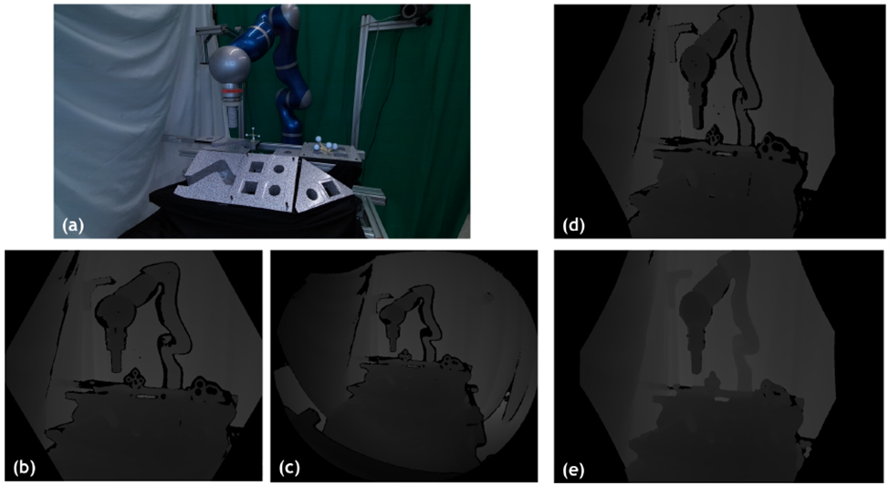 |
| Figure 10: (a) scene captured with Azure under various settings (b,c) with depth & RGB alignment (d) and KiRT (e) |
RayTrix acquisition
The left-middle of Figure 8 shows a non-conventional camera acquisition approach based on a so-called plenoptic camera, here the RayTrix camera. The scene is imaged through micro-lenses that act as small cameras that look at the scene from various viewpoints. The RayTrix Software Development Kit (SDK) then estimates the scene depth with a kind of multi-stereo depth estimation approach, providing a high-resolution color image and its aligned depth map into an RGBD data structure. This must be transformed into the RGBD data format used by RVS, requiring a couple of DLLs for the conversion.
System Hardware setup
Robotic setup with HMD
The interface between hardware and software has been done as shown in Figure 11, ending up with the complete setup shown in Figure 12 with input coming from the Azure Kinect and/or RayTrix cameras (cf. red and green arrows in Figure 8) and the virtual views being output to a TV screen or stereoscopic HMD. The OpenXR interface in Figure 8 (right) brings a lot of flexibility to also connect CREAL’s light field HMD, shown in Figure 13. Two generations of HMDs were used throughout the project; the first generation used in the beginning of the project, while the second generation with a much larger holographic field of view being finalized only at the end of the project. Both support Holographic Vision, cf. the example in Figure 8 (bottom-right) with focus on the foreground cubes (simulation of the eye accommodation).
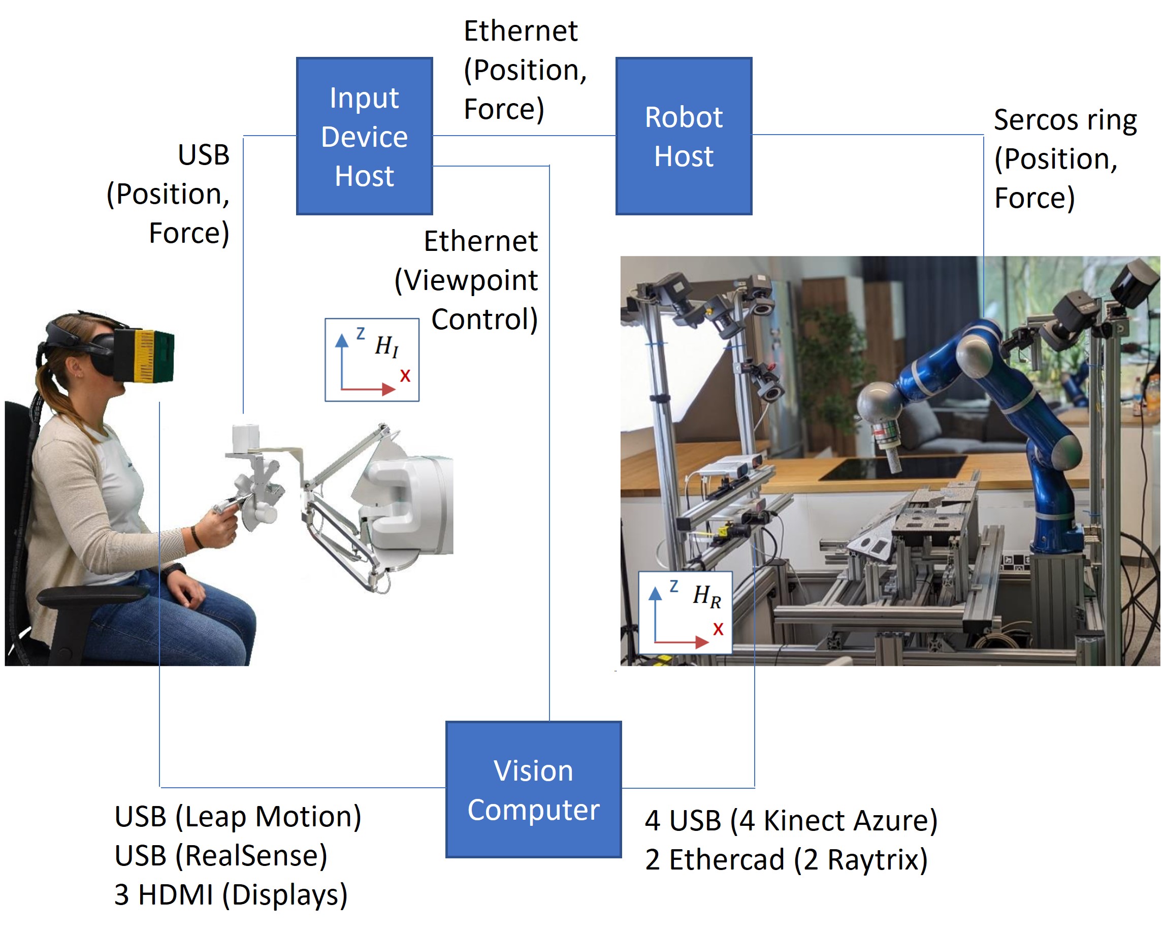 |
| Figure 11: Interfacing with the robotic setup. |
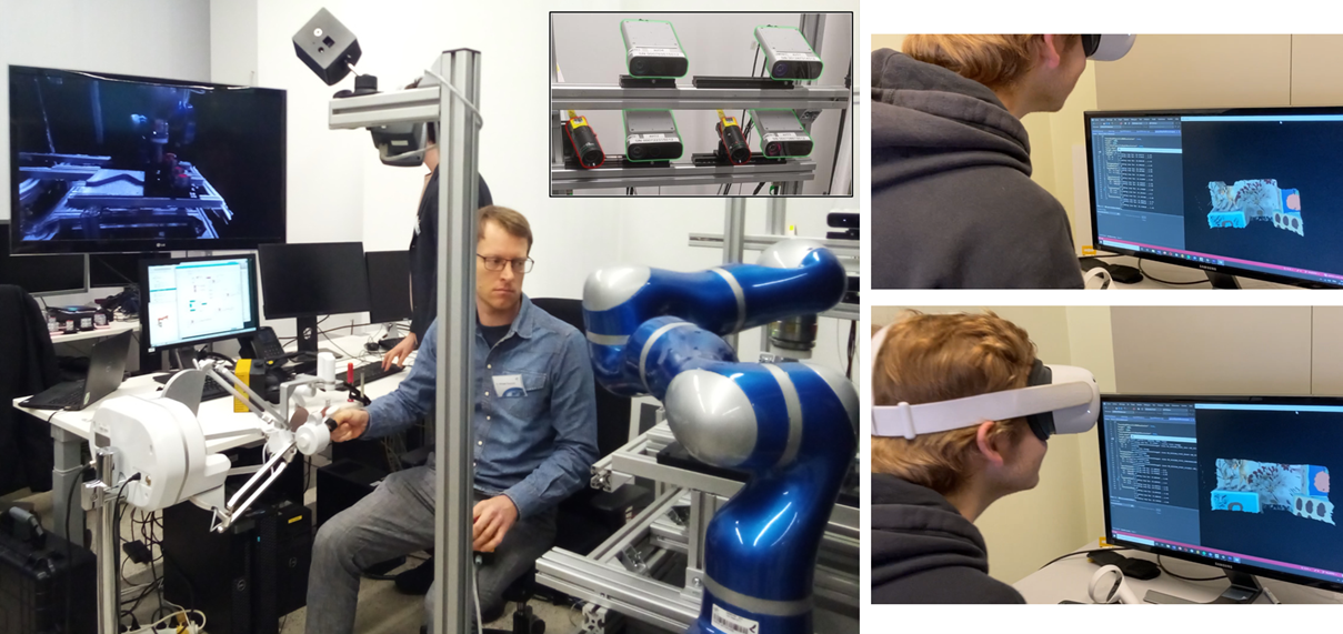 |
| Figure 12: Physical setup tele-operated (DLR) with rendering on screen (left) or head mounted display (ULB - right) using Azure and/or RayTrix capturing devices (top-center). |
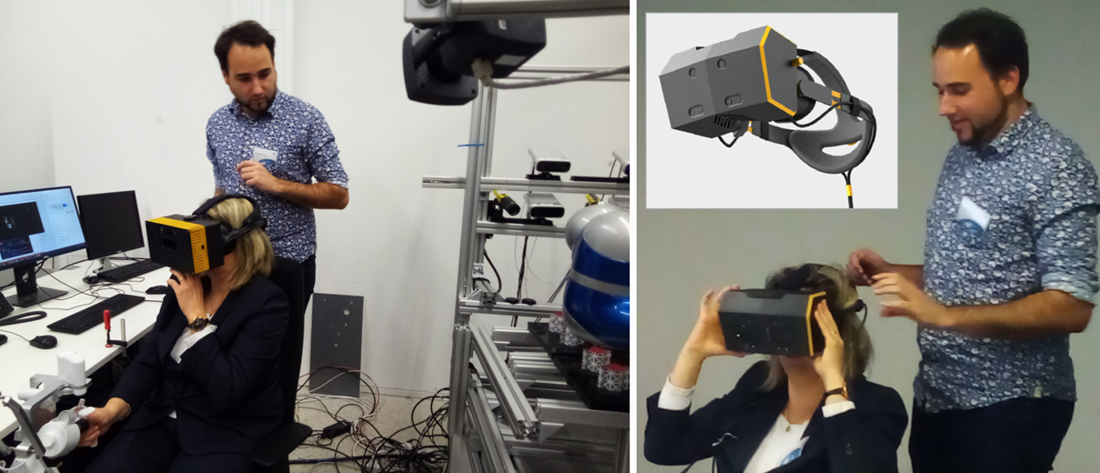 |
| Figure 13: Head mounted display providing Holographic Vision (CREAL): first generation (left) with relatively small light field fovea; second generation (right) with large holographic field of view. |
Multi-GPU servers
UPM and ULB performed multiple tests for the multi-GPU software development on their own multi-GPU servers, cf. Figure 14 and Figure 15, respectively.
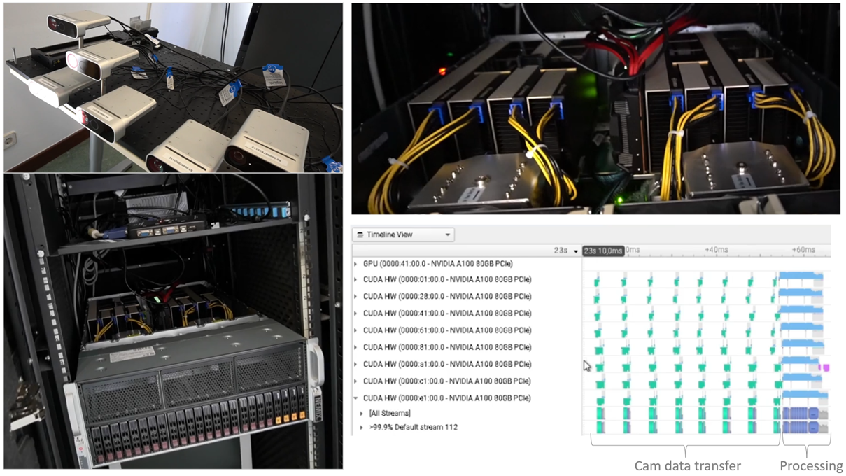 |
| Figure 14: : Multi(8)-GPU server at UPM (bottom-left, top-right) using 8 Azure Kinect input (top-left) for KiRT processing (bottom-right). |
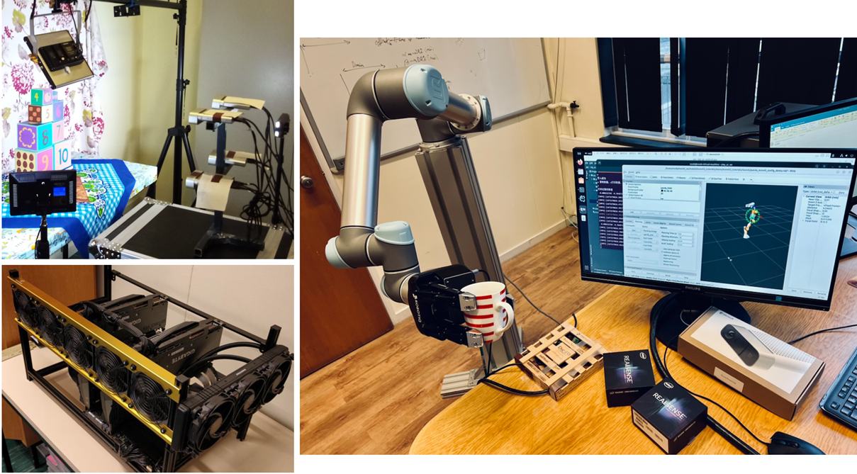 |
| Figure 15: : Multi(4)-GPU server at ULB (bottom-left) using 4 Azure Kinect (top-left) and robotic setup at ULB (right). |