Raytrix Acquistion DLL
This document explains briefly how the Raytrix Streaming DLL operates to acquire data, post-process it for further be used by the View Synthesis Module, and the data is sent to that module.
First, the Raytrix SDK and its metholodogy is explained, then how we use that SDK into the Raytrix Streaming DLL for the HoviTron Video Pipeline purpose.
Raytrix SDK
The Raytrix SDK is an API written in C++ which allows you to use Raytrix materials (cameras, ray files, sequence files,...) and compute different processes on a GPU with a CUDA environment. At this date, it exists six versions of the Raytrix SDK but your Raytrix license decides which version you can use and must be updated if you do not have access to one of these versions.
In the HoviTron Video Pipeline purpose, we only worked with the fifth version and the sixth version. The sixth version has a simpler syntax and some computation processes have been improved and speeded up. Since the versions must be used differently because of their different syntax, two versions of the DLL have been made. Meanwhile, It results in slight differences in the code and in the result.
In each version, different functionalities are available as the computation of images (focused image, processed image, total focus image, depth map, point cloud,...), calibration (metric, Micro-Lens Array (MLA), extrinsic, wavefront), exporting parameters (compute, view, camera, ...), and reading/writing files (ray, sequence, metadata, Raytrix preset, ...). Since the documentation of the Raytrix SDK is not well explained and it only exists a few code examples, the user learning phase of the SDK is slow. For these reasons, the methodology of Raytrix SDK will be explained differently than in the official documentation but we assume that the reader knows how plenoptic cameras work.
Methodology
The Raytrix SDK methodology can be divided into three parts: (1) Acquiring data with a camera or a file, (2) uploading and pre-processing of the raw image on the GPU, (3) user-asked computation via the API.
flowchart LR

  subgraph Acq["1. Acquiring data"]
    subgraph Cam["(a) Camera"]
    camfct1["WaitForBufferNotEmpty()"]
    camfct2["MoveDataBuffer()"]
    end
    subgraph Ray["(b) Ray file"]
    rayInfo[Data is already available]
    end
    subgraph Seq["(c) Sequence file"]
    seqfct1["GetNextFrame()"]
    end
  end

  camfct1 --> camfct2

    subgraph Upload["2. Upload + Raw data preprocessing"]
    uploadfct1["UploadRawImage()"]
    uploadfct2["(Hidden) PreProcess()"]
  end

  Cam & Ray & Seq --> Upload

uploadfct1 ---> uploadfct2

   subgraph comp["3. Compute process"]
   askcomp["Asked computation"]
   subgraph exaskcomp["Example:"]
    askcompfct1["Compute_TotalFocus()"]
    askcompfct2["Compute_Depth3D()"]
    askcompfct3["Compute_PointCloud()"]
    askcompfct4["..."]
   end
  end

  Upload --> comp

subgraph data["4. Get data"]
  subgraph cpudata["CPU"]
  cpupointer["DownloadImage()"]
  end
subgraph gpudata["GPU"]
  gpupointer["GetDevicePointer()"]
  end
  end

comp --> data
Figure 1: Flow chart of the Raytrix SDK methodology
The first step, cf. fig. 1.1, is to acquire data which means getting the raw image that a plenoptic camera can acquire. It exists two ways to do that: (a) using a Raytrix camera and (b, c) using a ray or sequence file that has been exported before with the Raytrix SDK. In both ways, the camera used to capture the scene must have been calibrated, at least the MLA and the metric calibration. Using a ray or sequence file instead of a plugged camera allows you to not reload the camera and compute parameters used by the SDK.
By using a plugged camera, the user must wait that the camera buffer is not empty, meaning that the camera has filled the buffer with some data, to move the data into another memory space that the user can handle.
If a ray file is used, the user has already the data in his hands. If a sequence file is used, the user must load the next frame of the sequence.
After acquiring the raw image, the second step, cf. fig. 1.2, is to upload the raw image to the GPU in a CUDA environment so that the SDK can process all computations on GPU. But, before allowing the computations asked by the user, the SDK pre-processed the data because some processes are needed for every other computation process and will need to be made in any case.
During the last step, cf. fig. 1.3, the user can ask for any computation (total focus, point cloud, depth map, ...) that he wants to the Raytrix CUDA instance. Then, either get the CUDA array of an image or download the memory of an image in the CPU memory.
Parameters
For each part of the methodology, parameters can be settled to improve efficiency, quality, or computation time. In the first part, where data is acquired, the parameters concern the camera like its exposure time, the information about the main lens and the MLA, the metric, and MLA calibration. These parameters will be used for further processing. The parameters used in the second part and third part are resumed in one single object and are given to the Raytrix CUDA environment. For example, it is possible to force the use of a specific data type, change the Raytrix depth algorithm used, and decide to fill or not the depth map.
Depth Map
With the Raytrix SDK, it is possible to compute different depth maps. Most of the time, people are familiar with the GUI of RxLive and adjust the depth parameters by cross-checking the quality of the colored depth map. Indeed, it is the faster way to assure the quality of the depth map but this colored depth map is false since the value of the depth has been scaled in order to see it. The correct depth map that must be computed is the Depth3D image.
This depth3D image is a four channels image where, respectively, the first (second, third) channel represents the x (y, z)-position of the object captured by the pixel in millimeters. The fourth channel is called virtual depth but should not be used. Moreover, the SDK allows exporting Depth3D images from different planes (e.g, the virtual plane to the reference plane). As the Raytrix developer suggests, we still suggest you work with the most used one: the Depth3D image computed from the undistorted view to the reference plane where the thrid channel gives the depth in millimeters from the reference plane to the object.
Raytrix CUDA array
Since the goal of the Hovitron project is to provide a real-time pipeline from capturing cameras to 6-DOF applications via HMD, speed is a major concern. That is why most of the operations are done in the GPU where parallelization is more important. One way to work with a GPU in a C++ environment is to use the CUDA API only available with Nvidia GPUs.
As mentioned before, the Raytrix SDK decided to use the CUDA API to speed up their computation which allows us to get the device (GPU) pointer of the resulting images to continue working with another CUDA environment. However, to optimize memory efficiency, Raytrix developers decided to add some padding to their CUDA array. If the array padding is not taken into account, it can result in a wrong read of the images. Fortunately, the SDK gives the pitch of the array which is the number of bytes in one row. From this pitch, it is possible to get the padding (number of padded pixels) by dividing the pitch by the number of bytes in one pixel minus the width of the image.
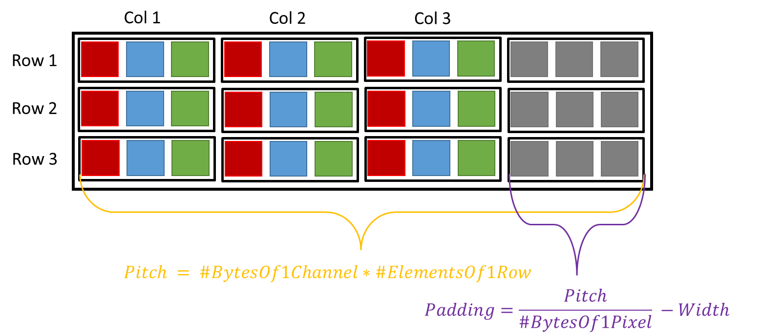
Figure 2: CUDA array padding
HoviTron Raytrix DLL
In comparison to the previous sections, this section aims to explain in detail the Raytrix DLL by explaining most of the functions of the DLL. Additional technical details can also be found in the header and source files of the Raytrix DLL: RaytrixStreamer.h and RaytrixStreamer.cpp.
Initialization
During the creation of the Raytrix streamer object, different initialization processes are launched where each of them has a different objective. Since the goal of each initialization part is straight forward, they are not explained here.
Here is the list of the initialization functions:
findVulkanGPUreadInfoFromJSONinitRxSDKinitRxCamsorinitRxRayFilesinitRxCudaComputeinitStreamParametersinitCudaArrayinitMutex
Acquiring Data
After the initialization processes have finished, the streaming loop is launched by the RVS thread. The first step is to acquire data. In the Raytrix DLL, it has been divided into two parts: (a) get the raw image on the GPU and (b) get the CUDA pointer of the arrays after computation.
(a) Load raw images on GPU
Since loading the data acquired by the cameras or the sequence files is done on the CPU, this process is slow and can bottleneck the pipeline. Therefore, the process is done asynchronously. While the streaming loop thread is post-processing the data, the data loading thread is working to make the data available when the streaming loop will need new data. It is straightforward that the first frame of each camera must be loaded before the streaming loop begins. However, the loading process is different if we work with plugged cameras or sequence files.
If sequence files are used, the loading thread will create a thread for each sequence file. In each of these threads, the next frame of the corresponding sequence file is loaded and then uploaded to the Raytrix CUDA instance. During that time, the loading thread waits until each sequence thread has finished its job to notice the streaming loop that the data has been loaded to the GPU. Note that we assume that the sequence files are already synchronized.
flowchart LR

subgraph loadThread["Loading Thread"]
waitStreamTh["waitStreamingThread()"]
createTh["createThreadForEachSeq()"]
waitTh["waitThreadsToFinish()"]
end

subgraph streamLoop["Streaming Thread"]
waitLoadTh["waitLoadingThread()"]
comp["Compute"]
end

subgraph seqTh["Sequence threads"]
th1["Thread 1"]
thi["..."]
thN["Thread N"]
end

comp -.-> dataMem(("Vulkan memory"))


waitLoadTh --> comp --> waitLoadTh

waitTh -.->|FINISH| waitLoadTh

comp -.->|FINISH| waitStreamTh

waitStreamTh --> createTh --> waitTh --> waitStreamTh

th1 & thi & thN -.->|FINISH| waitTh
Figure 3: Flow chart of the loading process for sequence files
Loading data from plugged cameras is more difficult since it needs synchronization between them. As before, the loading thread creates a thread for each camera. In this camera thread, it will wait until the buffer is not empty to copy the data in another memory space, as explained previously. If only one camera is used, no synchronization has to be done and the loading thread must wait for the single-camera thread to finish then upload the raw image and notice the streaming loop. If multiple cameras are used, a synchronization step is needed to make sure the frames have been acquired at the same time to prevent artifacts from moving objects. The loading thread waits until the reference camera (set as the first camera in the list) thread has finished its job, then wait for another camera thread to finish and compare the timestamp of the raw images. If the difference in the timestamps is too high, the loading thread starts from the beginning. If not, it continues checking the camera synchronization. If all cameras are synchronized with the reference camera, the loading thread uploads the raw images in the Raytrix CUDA instances and informs the streaming loop that data is available.
flowchart LR

subgraph loadThread["Loading Thread"]
waitStreamTh["waitStreamingThread()"]
createTh["createThreadForEachCam()"]
waitTh["waitThreadsToFinish()"]
checkSync["CheckSyncBetweenEachCam()"]
ok{"OK"}
nok{"Not Sync"}
end

subgraph streamLoop["Streaming Thread"]
waitLoadTh["waitLoadingThread()"]
comp["Compute"]
end

subgraph camTh["Camera threads"]
th1["Thread 1"]
thi["..."]
thN["Thread N"]
end

comp -.-> dataMem(("Vulkan memory"))

waitLoadTh --> comp --> waitLoadTh

ok -.->|FINISH| waitLoadTh

comp -.->|FINISH| waitStreamTh

waitStreamTh --> createTh --> waitTh --> checkSync

checkSync --> ok & nok

ok --> waitStreamTh
nok --> createTh

th1 & thi & thN -.->|FINISH| waitTh
Figure 4: Flow chart of the loading process for plugged cameras
(b) Get RGBD images
After the raw images have been uploaded on the GPU, the streaming loop can ask for the computation of the total focus and the Depth3D images to the Raytrix SDK. Then, we collect information about the CUDA arrays as the format, the pitch, the size, and the pointer.
Data Refinement
The second step of the streaming loop is to refine the RGBD images to improve the quality and make them readable by RVS. In Section 3.4, we explained that Raytrix pads their CUDA arrays for memory efficiency.
Thus, if an array has been padded, the padding is removed, if not, the array is copied to another device memory space. The total focus image only needs this padding removal process, but we need to extract the depth from the Depth3D image, then scale it in meters, and get the depth from the camera to the object instead of the depth from the reference plane to the object. Therefore, one CUDA kernel is used for these four operations: extract the third channel, convert it in the camera plane, scale it in meters, and remove the padding.
Temporal Consistency
The Raytrix depth can contain a lot of noise, even more, if the depth parameters are optimized for a fast depth computation as it is the case in the project. It can result in spikes artifacts which are uncomfortable for the user. To solve this problem, a temporal consistency algorithm is commonly used. This algorithm consists of reducing spike artifacts by comparing the depth of the current frame with the depth of the previous one.
More precisely, the algorithm computes the average absolute L1-norm of a patch around each pixel between the current and the previous depth. If the average error of a pixel is greater than a threshold, we consider that the pixel depth has changed and nothing happens. If not, the pixel current depth is updated with a combination of the current and previous depth. The process can be resumed by
Where \(\epsilon\) is the average absolute L1-norm in the patch, \(\tau\) is a threshold, \(\alpha\) the scaling factor, \(Depth_{curr}\) the current depth value, and \(Depth_{past}\) the depth value of the previous frame.
Preparing Data for transfer
The streaming DLL thread will prepare the data in the stream objects and the RVS thread can pick it up when it wants. The information about the images has been already filled during the initialization process, the last thing to prepare is the RGB and depth images. Thus, the streaming thread copies the images into two CudaSurfaceObject that can be read efficiently by the Vulkan API of the RVS thread.
To prevent race conditions, a CUDA event is recorded after this task.
Results
The Raytrix streaming loop DLL can run at most at 30 frames per second (fps) with one single camera:
And at most 20 fps with two sequence files simulating two Raytrix cameras: